This post will detail how to set up a RedBoard to have a light sensor that causes 3 different colored LEDs to light up depending on how much light the sensor senses.
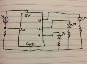
Below is the schematic for setting up the board:
Below is the code for the Arduino to run:
void setup() {
Serial.begin(9600); //This starts our light sensor
pinMode(LED_BUILTIN, OUTPUT); //This calls the 3 LEDs into operation
pinMode(12, OUTPUT);
pinMode(11, OUTPUT);
}
void loop() { //The loop will cause the program to run indefinitley
int sensorValue = analogRead(A0); //This is the variable supplied by the sensor.
Serial.println(sensorValue);
delay(1);
if (sensorValue > 650) // nothing in front of sensor = yellow light on
{
digitalWrite(LED_BUILTIN, HIGH);
}
else
{
digitalWrite(LED_BUILTIN, LOW);
}
if(sensorValue < 400) //finger in front of sensor = blue light on
{
digitalWrite(12, HIGH);
}
else
{
digitalWrite(12, LOW);
}
if(sensorValue > 400 && sensorValue < 600) //partial light blockage = red light on
{
digitalWrite(11, HIGH);
}
else
{
digitalWrite(11, LOW);
}
} //closes the loop
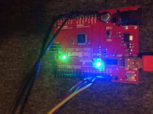
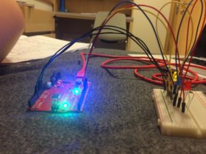
Below are pictures of the RedBoard and breadboard connected:
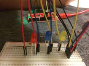
How to setup the breadboard and RedBoard:
- Run your first wire(black) from the 5V into row 1 of the bread board.
- Insert the first leg of the sensor into the same row as the black wire. (Row 1)
- Insert the second black wire into the same row as the second leg of the sensor. (Row 3)
- Run the second black wire back into the A0 port.
- Place a 10K resistor onto the row with the second leg of the sensor and the second black wire. (Row 3)
- Place the third black wire into the same row as the second leg of the resistor. (Row 5)
- Run the third black wire into the Ground Port.
- Place the first yellow, first blue, and first red into the same row as the third black wire. (Row 5)
- Create the chain for each light by placing the first wire on the same row as the first leg of it’s color corresponding LED light, the first leg of the resistor on the same row as the LED’s second leg, and the second wire in the same row as the resistor’s second leg.
- Then attach the second wire’s to the RedBoard: red to 11, blue to 12, and yellow to 13.
- Plug the RedBoard into a laptop using the USB cable.
- Run the Arduino code.
- If a light doesn’t light up, try switching the position of the LED legs.
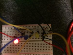
- Move your finger in front of the sensor and watch the lights change!