Foreword
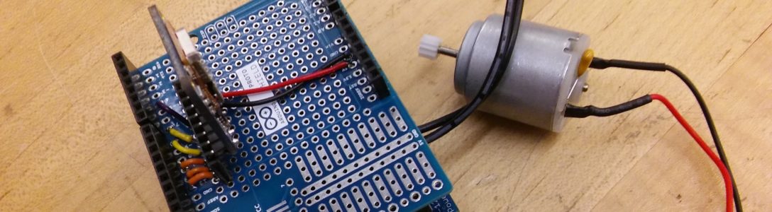
This is a replica of the circuit we made in class so building the circuit itself was not hard. The code was also similar to the one done in class so it was fairly easy to adapt it to control three LEDs. However, there were a few problems. The output received from the microcontroller was always 1023 (the max the LDR can output) for some reason. After trying other microcontrollers I determined mine was at fault somehow. In a panic, I pushed the reset button on my microcontroller and… it worked, THANKFULLY. With that out of the way, the next issue was apparently my breadboard, which had some connection issues. After some jiggling the wires eventually connected and everything was up and running.
Things I learned:
- I may need another new breadboard
- The reset button is your friend if somehow analog input is not working
Code
void setup() {
/*setting the pins that the LEDs will be connected to for digital
output and also set up the serial connection between the computer and
the microcontroller*/
Serial.begin(9600);
pinMode(12, OUTPUT);
pinMode(11, OUTPUT);
pinMode(10, OUTPUT);
}
void loop() {
//store the value from the microcontroller in an integer variable
int sensorValue = analogRead(A0);
Serial.println(sensorValue);
//if the value is greater than 300 only pin 12 gets a HIGH signal
//the other two pins receive LOW
if(sensorValue >= 300){
digitalWrite(12, HIGH);
digitalWrite(11, LOW);
digitalWrite(10, LOW);
}
//if the value is less than 300 but higher than or equal to 250
//only pin 11 gets a HIGH signal, the other two pins receive LOW
if(sensorValue < 300 && sensorValue >= 250){
digitalWrite(11, HIGH);
digitalWrite(12, LOW);
digitalWrite(10, LOW);
}
//if the value is less than 250 only pin 10 gets a HIGH signal
//the other two pins receive LOW
if(sensorValue < 250){
digitalWrite(10, HIGH);
digitalWrite(11, LOW);
digitalWrite(12, LOW);
}
//delay to not mess with the serial communication
delay(1);
}
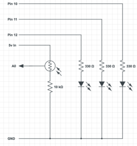
Circuit Schematic