For this assignment, I made a circuit that turns the LEDs off gradually when light intensity exceeds a certain bound (where the boundary is particular for each LED). I gave the LEDs different responses for different sensorValues and parameters. I used ‘if,’ ‘else if’ statements, ((sensorValue > x ) && (sensorValue < x )), and (sensorValue > x ) to create these parameters. For instance, for the green LED, when the sensor value is between 1-300 (as can be viewed in the serial monitor, which is set up in the code using Serial.print), the green LED is set to HIGH; when it exceeds 300, it is set to LOW.
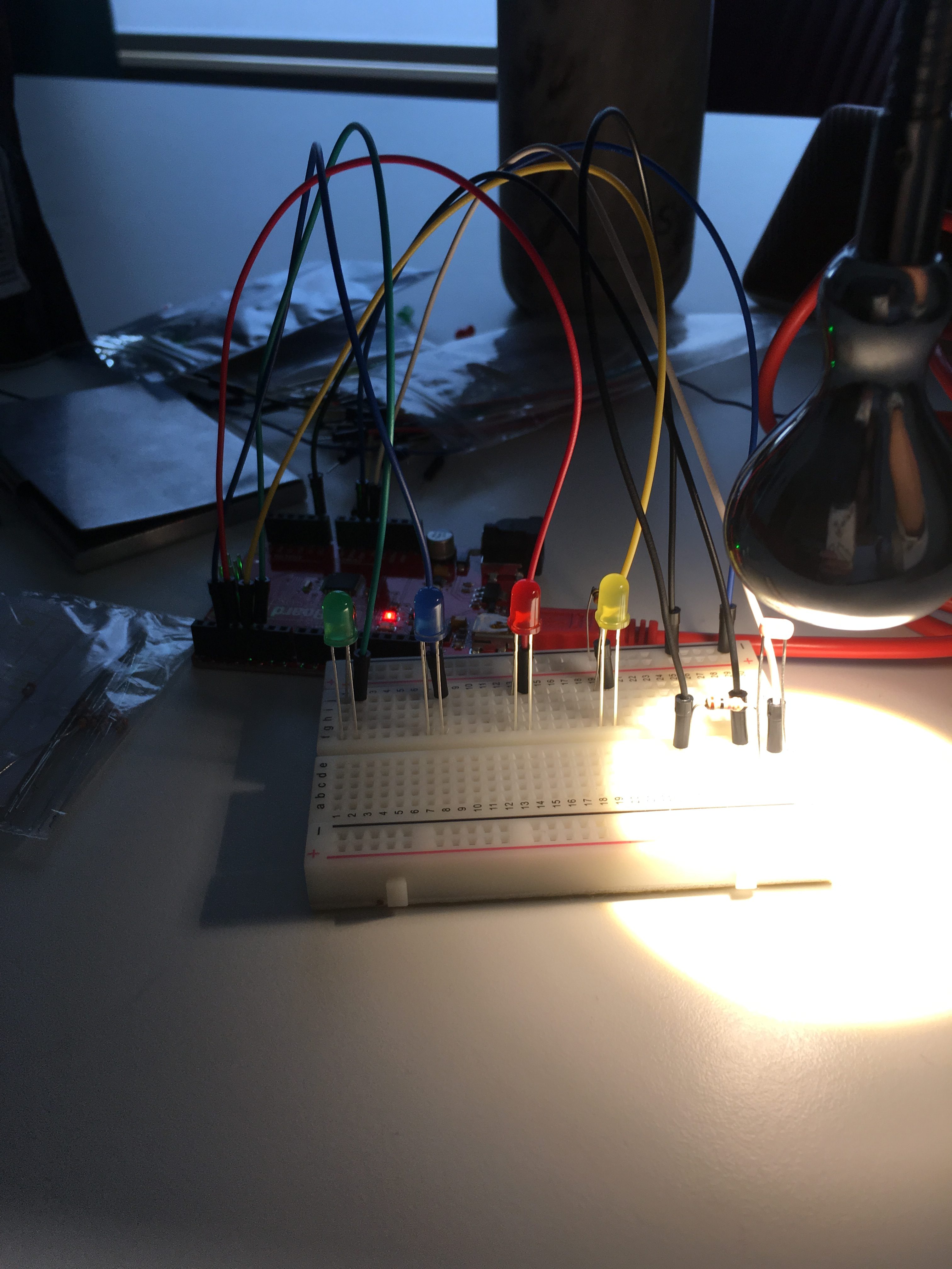
See below schematic, images, demonstration video, and code (which contains additional information) for further details.
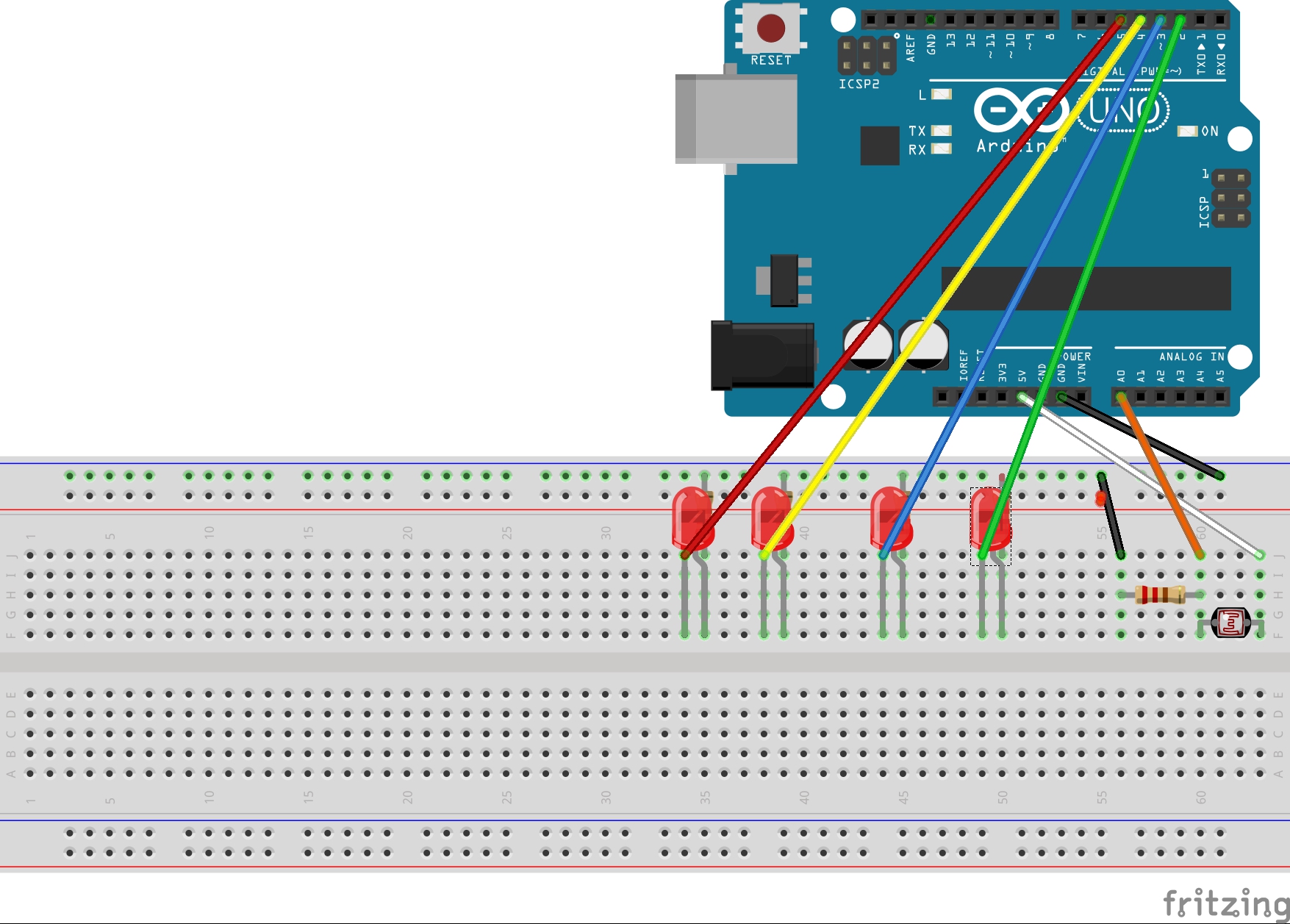
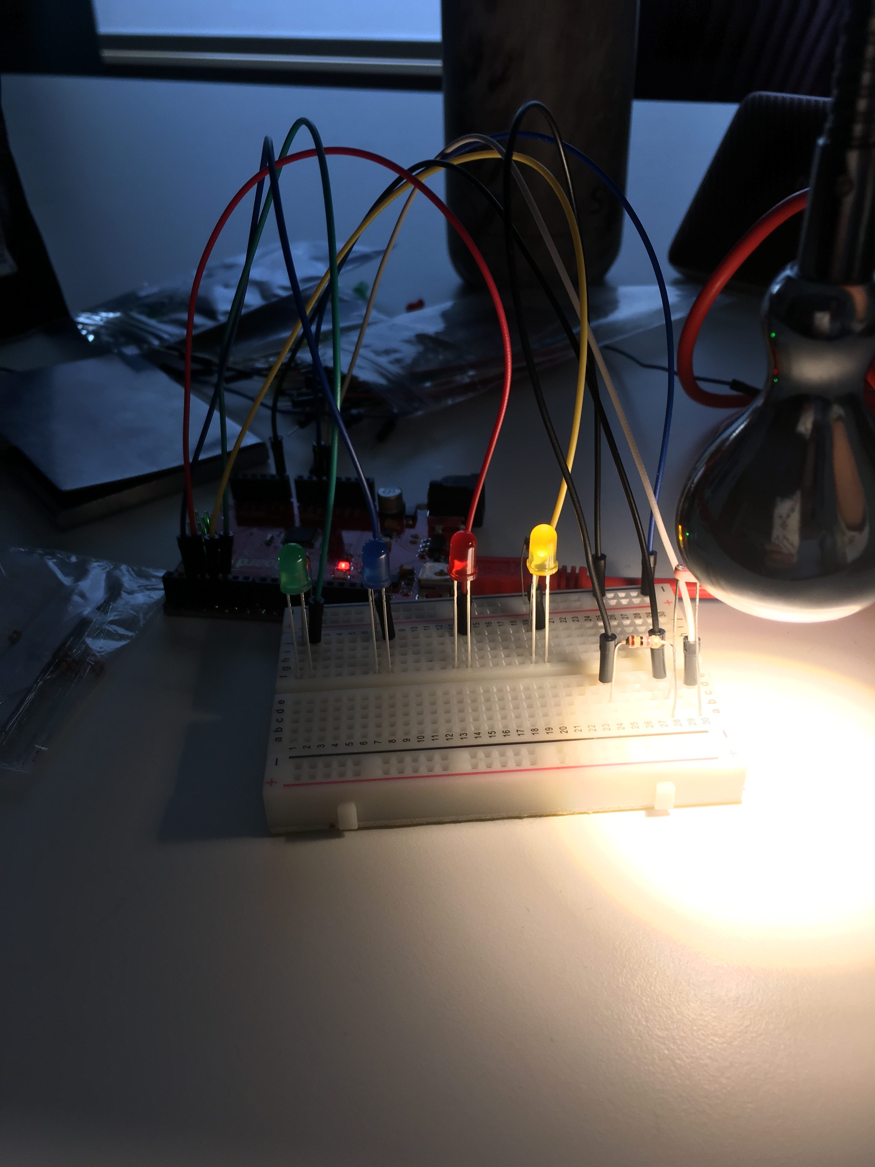
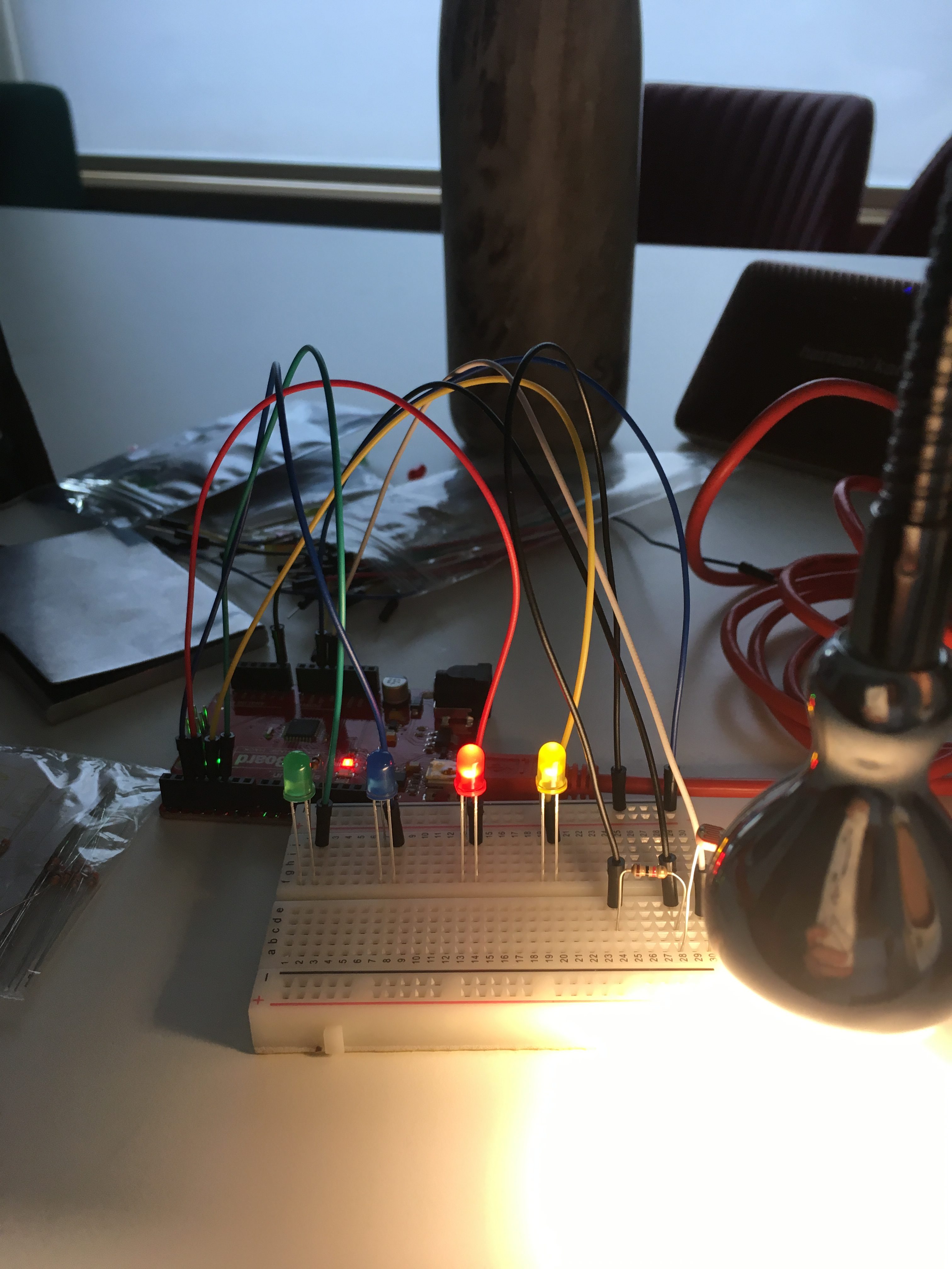
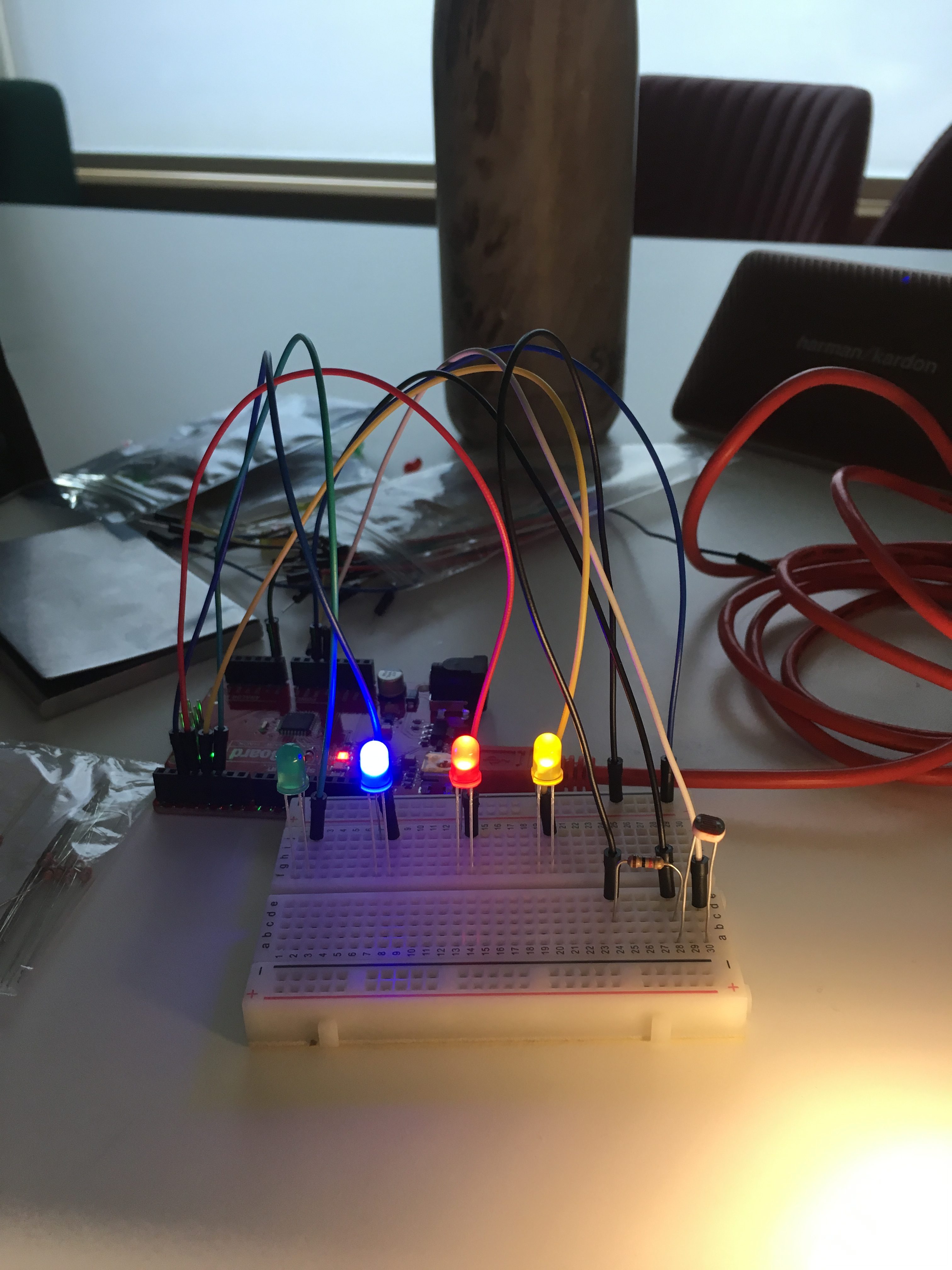
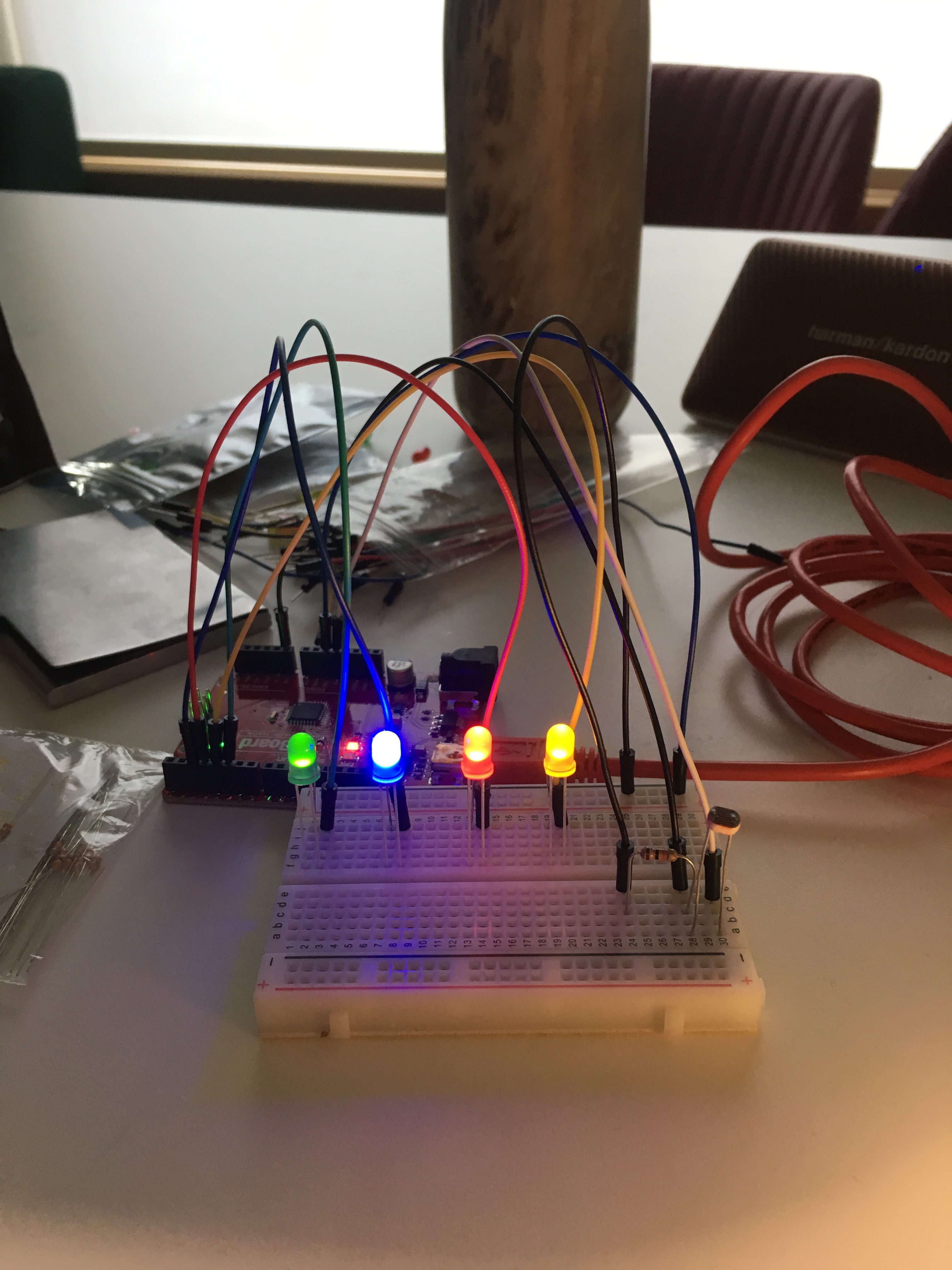
The below images show the LEDs gradually lighting up as the light source moves away from the LDR:
Watch it in Action \/ \/
CODE:
//label each of the pins according to the colour of their LED
int red = 3;
int blue = 2;
int yellow = 4;
int green = 5;
int sensorValue = 0; // value read from the LDR, initially set to 0
int outputValue = 0; //initial output value set to 0
void setup() {
Serial.begin(9600); //sets the baud rate to 9600 to coincide with that selected in the serial monitor
//define the LEDs as outputs
pinMode(red, OUTPUT);
pinMode(blue, OUTPUT);
pinMode(green, OUTPUT);
pinMode(yellow, OUTPUT);
}
void loop() {
int sensorValue = analogRead(A0); // read the value from the sensor
Serial.println(sensorValue); //prints the values coming from the sensor on the screen
delay(1);
// print the results to the Serial Monitor:
Serial.print(“sensor = “);
Serial.print(sensorValue);
Serial.print(“\t output = “);
Serial.println(outputValue);
delay(1);
{
if ((sensorValue > 1) && (sensorValue < 300)) { //create parameters of sensor value (in this case with the LDR, the sensor value is the light intensity)
digitalWrite (green, HIGH);
}
else { //if the sensor value is above 300, turn the LED off
digitalWrite (green, LOW);
}
}
{
if ((sensorValue > 300) && (sensorValue < 500)) {
digitalWrite (blue, HIGH);
}
else {
digitalWrite (blue, LOW);
}
}
{
if ((sensorValue > 600) && (sensorValue < 800)) {
digitalWrite (red, HIGH);
}
else {
digitalWrite (red, LOW);
}
}
{
if (sensorValue > 900) {
digitalWrite (yellow, LOW);
}
else {
digitalWrite (yellow, HIGH);
}
}
}